Synchronous amplifier for detection of modulated signals in the presence of significant noise. Compact package and two-button control for quick and easy configuration without compromising performance. Noise contributes negligibly in typical low-noise amplified photodetector (e.g., Eikonal TIA-F-01 and TIA-R-01) applications.
Regular price$684.00Sale price$684.00
Synchronous Amplifier
1 / of2
Scroll to section
Synchronous detection for weak signals
Low noise (10 nV/√Hz)
Adjustable gain: 20, 40, 60, 80 dB
Wide frequency range: 200 Hz–50 kHz
Simple, two-button control (gain/phase)
Low power, 24 V DC operation
TTL-like phase-reference input
Compact: 13 mm x 30 mm x 80 mm
Detection of chopped signals
Precision AC voltmeter
Low noise photodiode backend
Synchronous detection allows measurement of weak signals in the presence of wideband noise (e.g., 1/f or Johnson noise). By modulating or “chopping” the signal with known phase, the noise can be narrow-banded and shifted to higher frequencies where 1/f noise is insignificant. The adjacent block diagram shows schematically the principles of operation of the present module. The inputs to the amplifier are the modulated signal (green) and a square-wave sync reference (red), which has a fixed phase relative to the signal. The incoming signal is AC-coupled and amplified via the gain stage (blue). The reference is shifted in phase, 𝝋, to match that of the amplified signal (magenta) and used to route the signal alternately to an inverting and non-inverting input. The output (cyan) from this stage is a rectified version of the input. A low-pass filter suppresses the modulation and outputs the rectified signal as the cycle average (orange). Setting 𝝋 to zero is achieved by adjusting the phase until the output is nulled, then adding an an additional 𝛑/2 phase shift to recover the full signal.
Contact us to discuss custom solutions, pricing and lead-time. Example customizations include:
Time constant
Gain
Operating frequency range
Specifications
Gain Stage
Input impedance
1 MΩ
Gain settings
20, 40, 60 80 dB
Lower 3dB point
32 Hz
Upper 3dB point
20, 40 dB
700 kHz
60 dB
350 kHz
80 dB
50 kHz
Input saturation
16 x 10-dB/20 Vpp
Max input voltage
±10 V
Reference Phase Control
Frequency range
200 Hz - 50 kHz
Quadrature steps
0°, 90°, 180°, 270°
Fine phase range
0°–108°
Fine phase step
1.08°
Phase reference
VIL: 0-0.9 V VIH: 2.4-5V
Output Stage
ENBW
1 Hz
Settling time (99%)
0.83 s
Rolloff
12 dB / octave
Output noise
70 µV rms (at 80 dB)
Max output voltage
9 V (min load: 1.5 kΩ)
General
Signal connectors
SMA (in, out, ref)
Operating temp
5-30° C
Power
24 V DC @ 500 mA 2.5 x 5.5 mm barrel, positive tip
Aux output power
± 12 V @ 150 mA, M8 3-pin plug
10 nV Hz-1/2 Equivalent Input Noise
Measured output noise at the 80 dB gain setting as a function of modulation frequency. The model band spans the range of op amp noise. The gray horizontal line is the 1/f noise contribution from the output filter. The synchronous amplifier will contribute negligibly to the error budget when paired with a typical low-noise transimpedance amplifier.
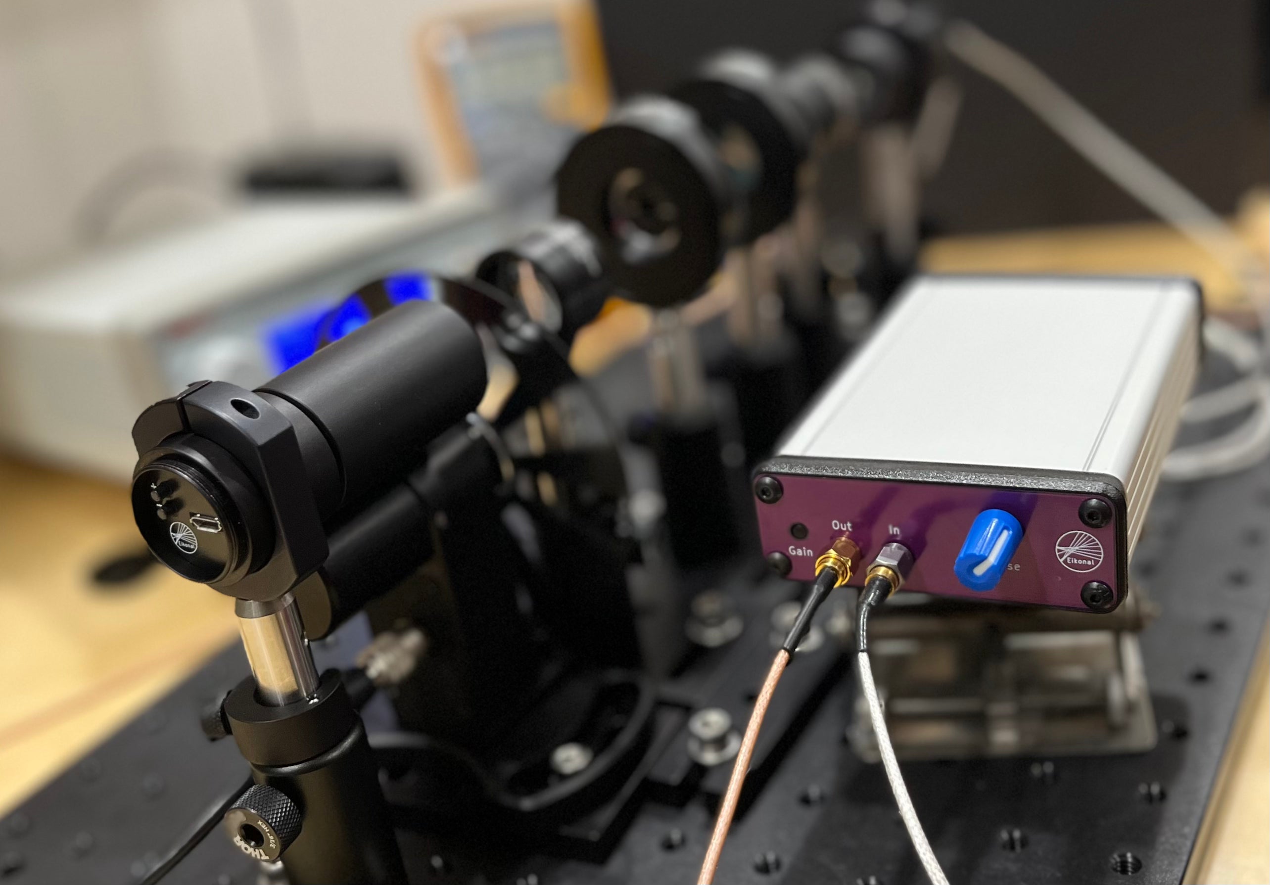
Back panel, showing phase reference input, input 24 V power, and ±12 V output power. The ±12 V output is generated entirely from analog (non-switching) components and integrates with the Eikonal amplified photodiode (TIA-F-01). Consistent with the compact profile and two-button interface philosophy, this feature adds further convenience, saving on set-up time and bench space.
High Dynamic Range Optical Density Measurement with a Synchronous Amplifier
In this video, we’ll use a synchronous amplifier (Eikonal SA-01) to make high dynamic range measurements of the transmission of an optical component. We’ll use a modulated laser diode (Eikonal LDFC-01) as a light source, and a large area amplified photodiode (Eikonal TIA-F-01) as the photodetector. In this example, we’ll measure the optical transmission of laser safety glasses. We'll use the Eikonal modules as a system to make measurements sensitive to a part in 10,000.
Choosing a selection results in a full page refresh.