Generally, noise is any unwanted signal such as interference from a switching power supply or a WiFi router. These types of external noise can often be reduced or even eliminated by moving the source or adding appropriate shielding. However, some types of noise are intrinsic and unavoidable, even in a circuit made with ideal components. Quantum mechanical shot noise is a well known example. Shot noise is evident at low light levels when individual photons (and corresponding photoelectrons) comprising the signal can be discerned.
Johnson noise is perhaps less familiar but also ubiquitous because it is a type of noise that is associated with resistors. Historically, the discovery of voltage and current fluctuations in a resistor was made at Bell Labs in the 1920s. Measurements by J. B. Johnson were subsequently explained by H. Nyquist.
Johnson noise sets a threshold against which signals must be discriminated. Johnson noise is present at any temperature above absolute zero. It is therefore helpful to understand its origin and nature so its effects can be minimized.
Johnson Noise and Dissipation
A resistor is an ohmic device that introduces a voltage drop when current flows and necessarily dissipates electrical energy as heat. On a microscopic level, the action of a resistor is a result of collisions between charge carriers and the conducting material of the resistor. These collisions impede current flow and transfer electrical energy to vibrational energy of the atomic lattice (heat). Like all physical processes, the transfer of energy from a charge carrier to the lattice must have an inverse. Thermal motions can therefore excite fluctuations in the energy of charge carriers, which appear as current and voltage fluctuations unless the resistor is at a temperature of absolute zero (0 K). Notice the importance of dissipation: ideal capacitors and ideal inductors do not exhibit Johnson noise.
In principle, the nature of Johnson noise can be inferred from a detailed physical understanding of the transport of charge carriers and their interaction with a given material. However, Nyquist showed this is not necessary, as the properties of Johnson noise can be understood in terms of the statistical mechanics of a transmission line.
Thermal Noise in an \( RC \) Circuit
Consider a circuit consisting of a capacitor, \(C\), and resistor, \(R\), connected in parallel. In this example the resistor is enclosed in a heat bath at absolute temperature, \(T\). The circuit experiences thermal fluctuations as energy is exchanged between its components.
According to classical statistical mechanics, the principle of equipartition says that the average energy of each degree of freedom is \( k_B T/2\) , where \(k_B\) is Boltzmann's constant. Our \( RC \) circuit has a single degree of freedom associated with the energy stored in the capacitor carrying charge, \( q\). This energy is: \[ E = \frac{1}{2}\frac{q^2}{C} =\frac{1}{2} C V^2 .\]
Using angle brackets to denote time averages, \[ \langle E \rangle =\frac{1}{2} C\langle V^2 \rangle , \] and from equipartition \[ \frac{1}{2} C\langle V^2 \rangle = \frac{1}{2}k_B T.\] or \[ \langle V^2 \rangle = \frac{k_B T}{C} . \] Equivalently, the fluctuating charge on the capacitor is \[ \langle q^2 \rangle = kT_B C , \] which is why the Johnson noise appearing on a capacitor is sometimes called "kTC" noise.
To find the variance (standard deviation squared) we use \( \sigma_x^2 = \langle x^2\rangle - \langle x\rangle^2 \). In this example, the average charge and average voltage are both zero because both positive and negative charge fluctuations are equally likely. Therefore, \( \sigma_q^2 = \langle q^2\rangle \) and \( \sigma_V^2 = \langle V^2\rangle \).
Counterintuitively, the value of \( \langle V^2 \rangle \) for Johnson noise is independent of \( R \). The Fourier spectrum of voltage fluctuations on the capacitor, \( S_V^C(f) \), occurs over a range of frequencies. If \( R \) is large, the bandwidth of the \( RC\) circuit is small. For the total rms to be independent of \( R\), as we have just found, the amplitude of the spectrum of voltage fluctuations must be proportional to \( R\). Thus the fact that the expression for \( \langle V^2 \rangle \) only references \( C\) does not mean that the capacitor is the source of Johnson noise. Alternatively, we could have arrived at the same conclusion about the spectrum by considering current fluctuations in a resistor paired with an ideal inductor, implying that the resistor and its associated dissipation is always the noise source.
The Spectrum of Johnson Noise
The variance of the voltage on the capacitor is related to the power spectral density of voltage fluctuations by \[ \langle V^2 \rangle = \int_0^{\infty } |S_V^C (f)|^2 \; df , \] where \( |S_V^C(f)|^2 = S_V^C(f) S_V^C(f)^*\) and the symbol \( * \) denotes the complex conjugate.
We now have to relate the voltage fluctuations that appear on the capacitor with the voltage fluctuations that arise in the resistor. As shown in the figure below, imagine replacing the resistor and its heat bath with its Thevenin equivalent of a perfect noise-free resistor in series with a voltage noise source described by the Fourier spectrum, \(S_V^N(f) \).

The transfer function, \( H(f) \), relates the the voltage across the capacitor to the applied voltage from the noise source, \( H(f) = S_V^C(f) /S_V^N(f) \). The resistor and capacitor form a voltage divider for which the transfer function is \[\begin{eqnarray} H(f) & = & \frac{1/(i2\pi f C) }{1/(i 2 \pi f C) + R} \\ \\ & = & \frac{1}{ 1 + i 2 \pi f RC}, \end{eqnarray}\] with \( i = \sqrt{-1} \) .
Using this result we have \[ \frac{k_BT}{C} = \int_0^\infty |S_V^N H(f)|^2 \; df . \]
The voltage fluctuations in the resistor are uncorrelated in time, so the associated power spectral density of fluctuations is constant with frequency and can be taken outside of the integral, \[ \frac{k_BT}{C} = |S_V^N|^2 \int_0^\infty \left| \frac{1}{ 1 + i 2 \pi f RC} \right| ^2 \; df , \] where the definite integral evaluates as \[ \int_0^\infty \left| \frac{1}{ 1 + i 2 \pi f RC} \right| ^2 \; df = \frac{1}{4RC}. \] This integral yields a quantity known as the equivalent power bandwith \( \Delta f = 1/(4 R C)\) for a single pole \(RC\) filter. Note, this is distinct from the 3 dB point which is defined by \( |H(f_{3dB})|^2 = 1/2\) or \( f_{3dB} = 1/(2 \pi RC)\).
From these results we conclude that the power spectral density of Johnson noise is \[ \boxed{|S_V^N|^2 = 4 k_BT R .}\] The SI units of \( |S_V^N|^2\) are \(\rm{V}^2\; {Hz}^{-1}\).
Referring back to the original equipartition argument we can see that the result for the voltage fluctuations on the capacitor can be written with explicit reference to the resistor value as \[\begin{eqnarray}\langle V^2 \rangle & = & 4k_BT R \Delta f \\ & & \\ & = & \frac{ k_BT R}{ \tau } . \end{eqnarray}\] Thus, as stated before with smaller bandwidths or longer time constants, \(\tau = RC \), the precision improves. This is related to our assumption that the Johnson noise fluctuations are uncorrelated in time and that averaging independent measurements reduces the standard error as the square root of the number of measurements or equivalently as the square root of the total integration time.
Numerical Values
Often the results for a noise spectrum are quoted in as the square root of the power spectral density since the units are volts per root hertz not volts squared per hertz and perhaps easier to compare with a signal measured in volts. In this convention the numerical value of the Johnson noise spectrum is \[ | S_V^N| = 41 \left( \frac{ R}{100 \; \rm k\Omega }\right)^{1/2} \left( \frac{T}{ 300 \; {\rm K}} \right) ^{1/2} {\rm nV}\ {\rm Hz^{-1/2}} ,\] where the scaling is from adopted convenient values of \(R\) = 100 k\(\Omega\) and \(T \) = 300 K.
Application to a Transimpedance Amplifier
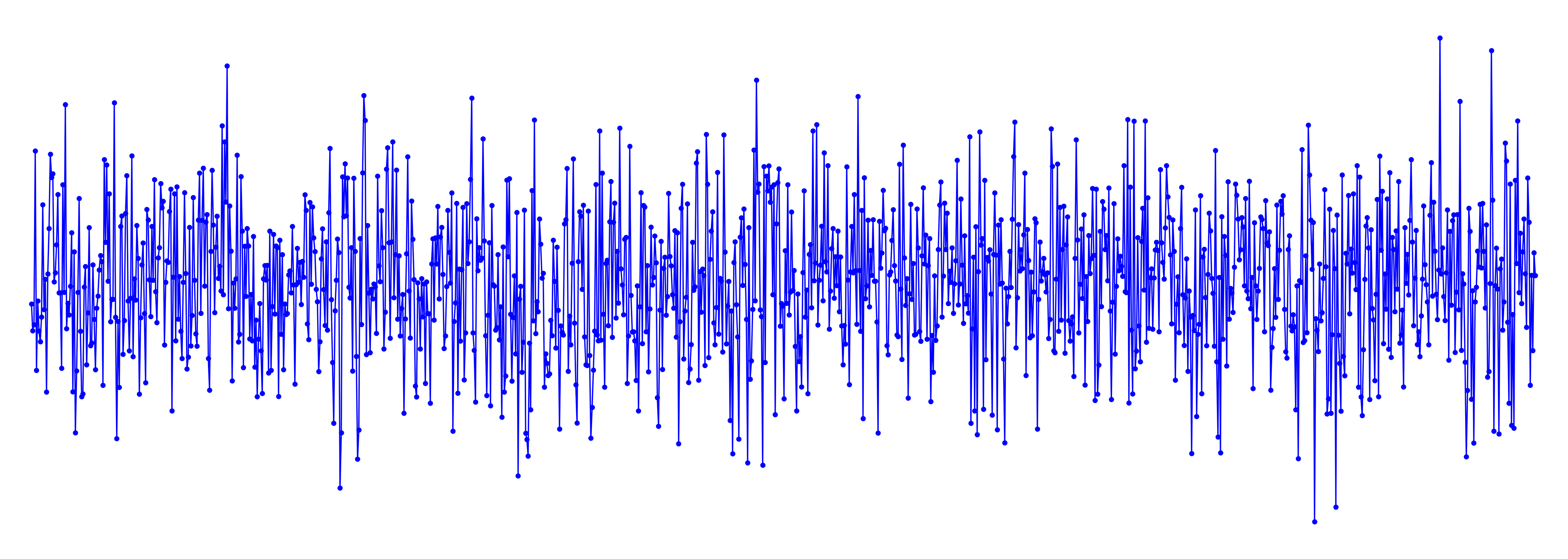
In a transimpedance amplifier (TIA), the feedback resistor, \( R_{\rm fb} \), converts photocurrent, \( I_{\rm phot}\) , into a voltage signal as \[ V_{\rm phot} = I_{\rm phot} R_{\rm fb},\] and the gain of a TIA is variously quoted as volts per amp or in ohms. This resistor introduces Johnson noise. In the Eikonal TIA-F-01 transimpedance amplifier, this resistor has a value of 330 k\( \Omega \) and a corresponding noise of \[ | S_V^N| = 73\ \rm{nV } \ \rm{Hz}^{-1/2}\] at room temperature (20\(^\circ\) C), which is the grey horizontal line shown on the measured noise plot. Note that the although the Johnson noise is proportional to \( R^{1/2} \) the signal is proportional to \(R\), hence the signal-to-noise ratio increases as \( R^{1/2}\). Thus, \(R\) should be made as large as possible, consistent with the desired bandwidth. In this example, the TIA-F-01 is limited only by Johnson noise at frequencies below 100 kHz.
\( k_B T C \) Noise and Correlated Double Sampling
In a photon-counting or integrating detector, which uses a capacitor to accumulate charge, e.g., a CCD, the rms error in units of the electron charge, \(q_e\), is \[ \begin{eqnarray}\sigma_e & = & \frac{\sqrt{k_BTC}}{q_e} \\ &=& 401 \left(\frac{C}{pF}\right)^{1/2} \left(\frac{T}{300~ K}\right)^{1/2}\; e^- \rm{rms} . \end{eqnarray}\] A 1 pF capacitor at room temperature has rms charge fluctuations corresponding to about 400 electrons. This seems to set a severe detection limit if we want to detect individual photons. However, if the integrating capacitor is isolated from the rest of the circuit while integrating (\(R\) is very large), the bandwidth becomes very small and the any fluctuation on the capacitor becomes fixed on very long timescales. Thus, the expedient of double correlated sampling, where the voltage on the integrating capacitor is measured before and after the integration defeats Johnson noise.
Notes & Further Reading
The derivation here is based on J. R. Pierce, "Physical Sources of Noise," in Proc. IRE, vol. 44, no. 5, pp. 601-608, 1956.
A history of electrical noise measurements and a rigorous derivation are in D. Abbott, B. R. Davis, N. J. Phillips & K. Eshraghian, "Simple derivation of the thermal noise formula using window-limited Fourier transforms and other conundrums," in IEEE Transactions on Education, vol. 39, no. 1, pp. 1-13, 1996.
Nyquist's approach to deriving Johnson noise is outlined in §17.5 of B. E. A. Saleh & M. C. Teich, Fundamentals of Photonics, Wiley
The spectrum of Johnson noise is found using the classical equipartition law similar to that used in the derivation of the Rayleigh-Jean's law for black-body radiation. The current result is valid only a "low" frequencies, i.e., below THz at room temperatures. At high frequencies or low temperatures, the classical value is modified by a correction factor of \(x/(e^x-1)\), with \(x=hf/k_BT\). This topic is discussed in our discussion of photon statistics.
© Eikonal Optics